
History:
Doug Duell Motorsports
The Screamin’ Woody was finished in 2006, and while most of the car was restored or rebuilt in 2018 – the wiring was not touched. From September 2021 to September 2022 (mostly that long because of supply shortages like custom pistons bigger than 4.5″) the car was at the shop of my bud Doug Duell. Doug watched me fight dependability issues with the drivetrain for two years and offered to let me use his guy Matt to pull the engine and take to Jeff Taylor’s, with a couple of Doug’s engines for a rebuild. He also took my trans to Rick Allison with his, for a thorough going through and update to the best of the best. Matt also ordered and replaced the driveshaft with a 4″ Victory.
I picked the car up in September, just in time for the Moparty and the Dave Duell Classic. As Matt was going over what he’d done – he pointed out that the car needed brake pads, a converter freshening and especially wiring. He said the wiring was a complete nightmare. Matt had pulled the fan off the transcooler and removed the 16v to 12v stepdown – but gave up there – as it was so bad that it required a complete rewiring.
Moparty and Dave Duell Classic
I raced it at Moparty, and the car has never been faster, but it wasn’t bringing the front wheels up evenly. The car kinda looking like an early 60s Chevy launching.

I tried shock and wheelie bar adjustments, but they didn’t help.
The following week was the Dave Duell Classic. There I started to develop a noise coming from under the car that was getting worse with each pass. Its frequency increased with speed. It looked like the weight on the new Driveshaft was just nicking the driveshaft loop, but it also sounded a lot like a rear gear crapping out. A couple Racers took a ride with me, but they too couldn’t put their finger on it – and all of them said “Run it!”. I decided to pull out of competing in the “All-Star” race to save the car for the finals. I lost in the second round of the “Finals”. That was the end of my NSS season, and time to make car better for 2023.
Back at My Shop:
When we returned home from the Finals, I ordered a new converter from ATI, and brake pads from Summit. When the Chunk was pulled to inspect, it was found to be missing teeth – and I suspect one more round would have been bad. Since I was changing from 33X10.5 slicks for 31X10.5 slicks, I ordered a Pro Gear 4.56 to replace the crumbling 4.71.

The new brakes, gear change and converter have been completed. It was found that the Anti-roll assembly was worn out. All of the years of hard launches had taken their toll and the bolts wallowed out the bolt holes – creating slop. I ordered a new assembly and that’s a story for another day. I also pulled the entire interior, installed a new headliner, painted the inside trim, painted the cage, dyed the seats from red to black and ordered carpet and door panel material. I’m still working on that. Finally, as I had previously reported, all of the Lexan was removed, and scratch resistant Lexan was installed with #10 stainless screws into rivet nuts.
However, this is report is about the Wiring
I bought a wiring kit from K&R. The beauty of this kit is that a single low voltage cable runs from the Switch panel to a Circuit Board with the relays, fuses and other circuitry. You wire all of the accessories to the circuit board and the switch panel also plugs into it.

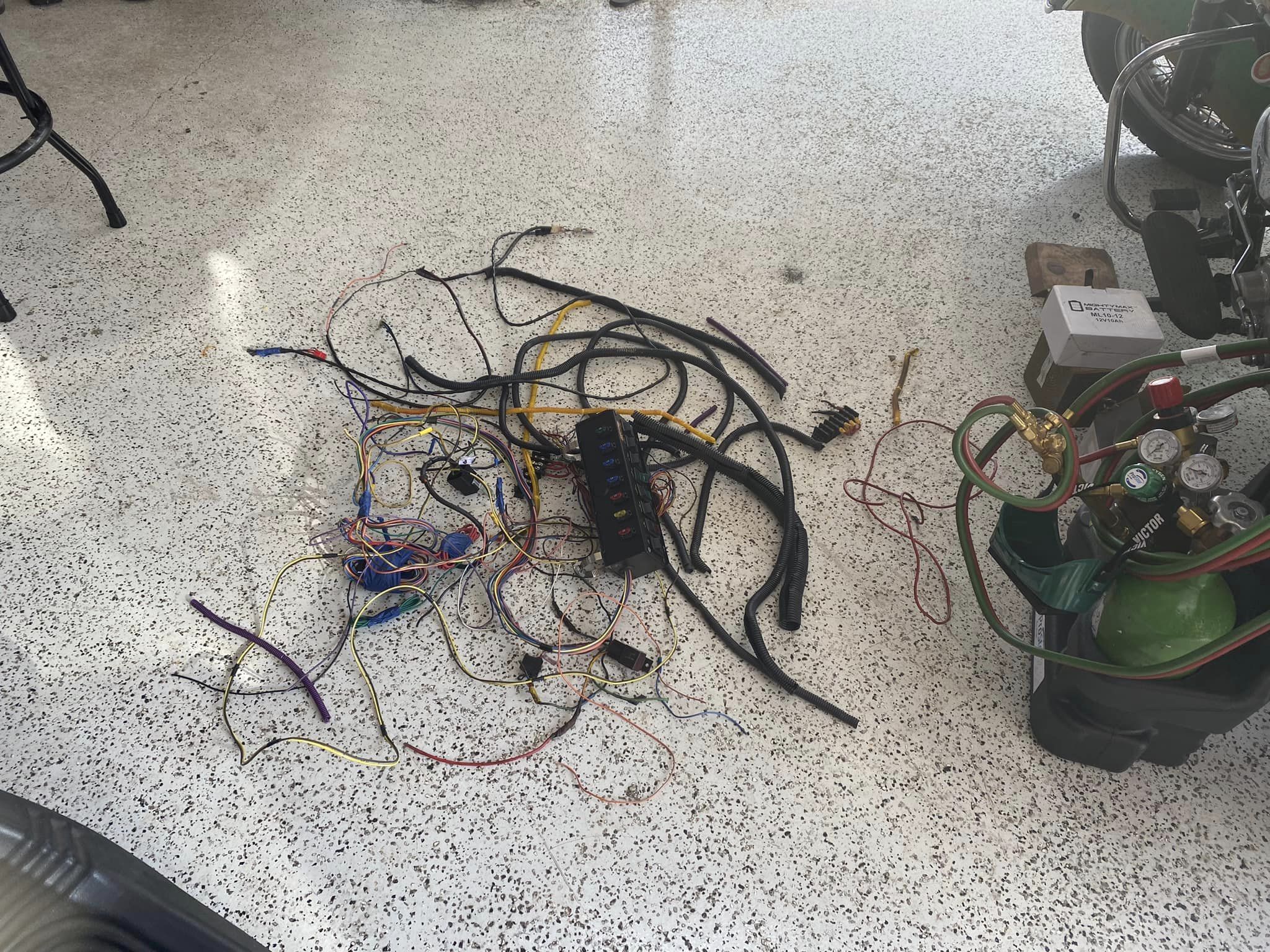
The first order of business was to identify the wires going to gauges, playback tach, roll control, shift light and other wires that needed to stay. Then rip out all the rest with buss panels and relays. The below are some photos of what I was faced with.


When I was finished pulling wire and installing the switch panel in a roll cage box (I didn’t have a large enough flat are on the dash to mount it), it looked like this.


Next, I needed to figure out where I was going to mount the Circuit Board and power distribution blocks. I figured the best place was the front opening on the door X-brace on the Passenger side. Gussets with all-thread was TIG welded where the bars met.


Next, I went and bought a 15″X18″X1/16″ aluminum plate. I measured, cut, smoothed the edges, drilled mounting holes, mapped where I was going to mount the circuit board and buss blocks, drilled for them, cleaned/prepped, sprayed with black primer, and finally slathered with the same hammered black paint I had used on the cage. After the paint dries, I’ll begin the process of bench wiring the circuit board and directionally route the wires into three groups under the board, mount the board to the plate I had made, and bundle to and wire up all electrical accessories. Prior to that, I’ll lay the carpet. Some photos if the mounting plate for the circuit board.


So, this is where I’m at now. Stay tuned for Part 2, which will be the completion.